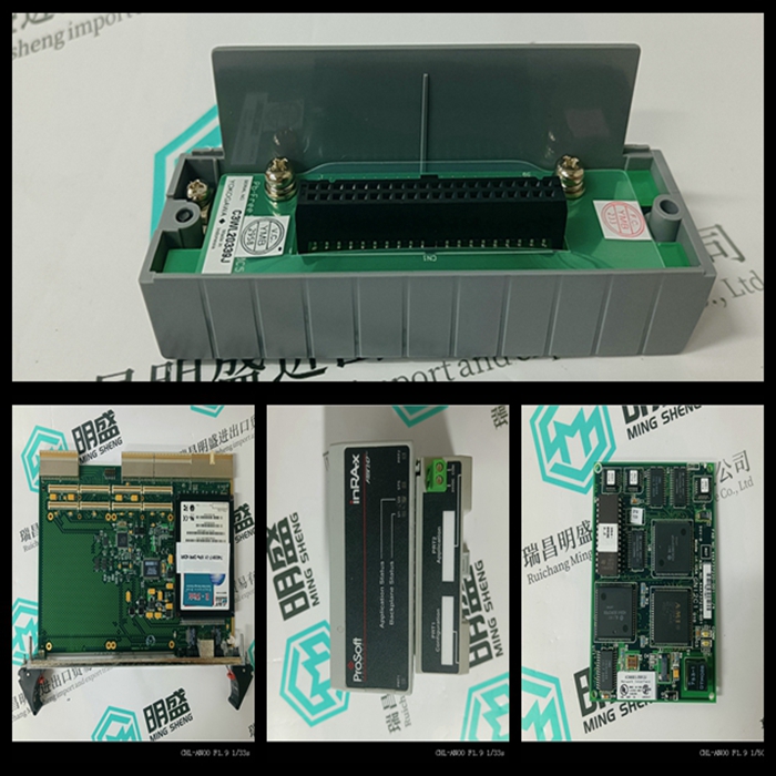
SAIA pcd2.m150控制模块怎么使用
类目:其他
型号:pcd2.m150
全国服务热线:+86 15270269218
手机:+86 15270269218
微信:+86 15270269218
QQ:3136378118
Email:stodcdcs@gmail.com