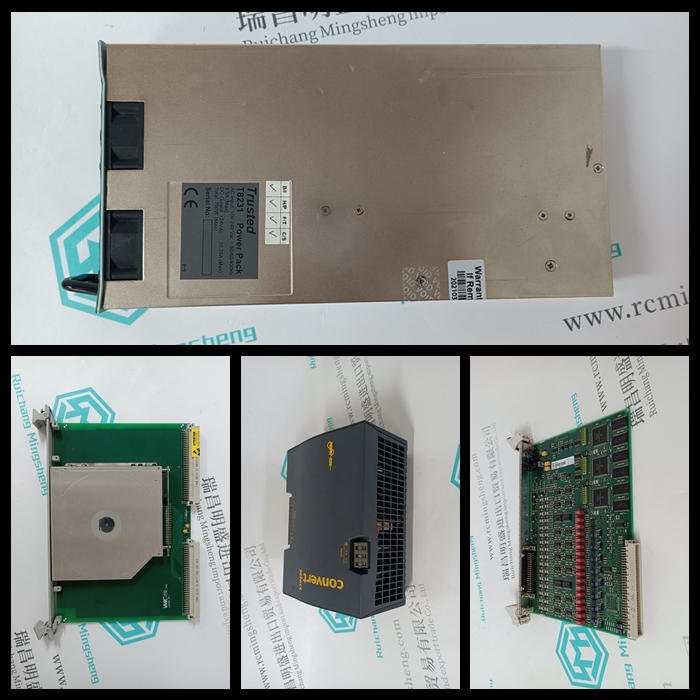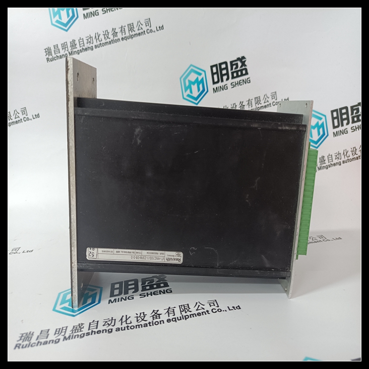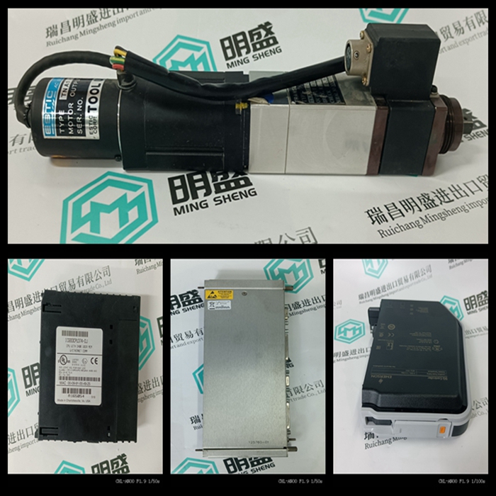
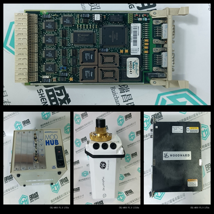
Rexroth R911285509 MHD115A-024-NP0-AN伺服模块备件
类目:力士乐
型号:R911285509 MHD115A-024-NP0-AN
全国服务热线:+86 15270269218
手机:+86 15270269218
微信:+86 15270269218
QQ:3136378118
Email:stodcdcs@gmail.com