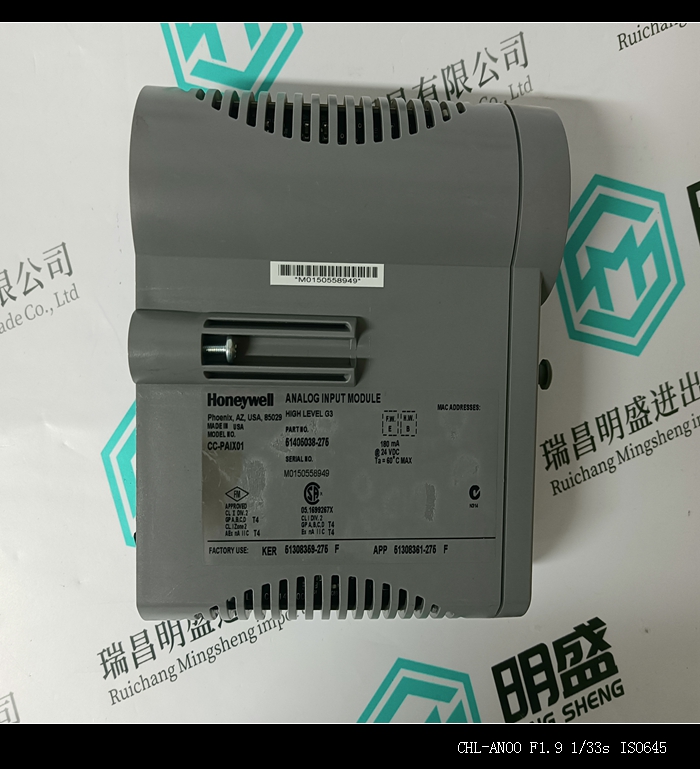


HONEYWELL MU-KFTA20模块PLC系统工控备件
类目:HONEYWELL霍尼韦尔
型号:HONEYWELL MU-KFTA20
全国服务热线:+86 15270269218
手机:+86 15270269218
微信:+86 15270269218
QQ:3136378118
Email:stodcdcs@gmail.com