
1D54471G02库存PLC模块卡件工控备件
类目:EMERSON艾默生
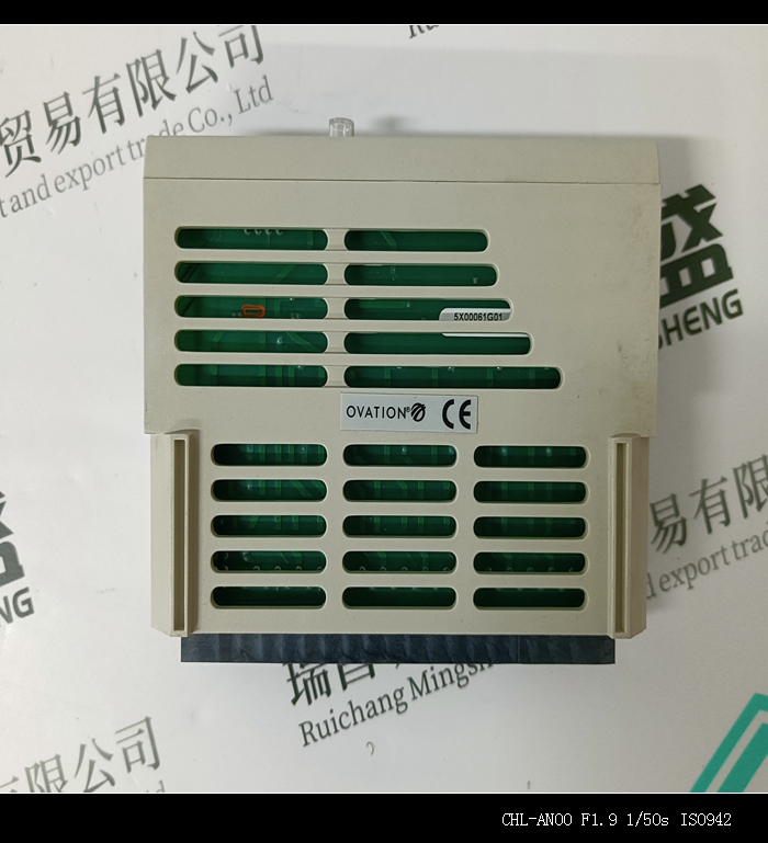
型号:1D54471G02
全国服务热线:+86 15270269218
手机:+86 15270269218
微信:+86 15270269218
QQ:3136378118
Email:stodcdcs@gmail.com