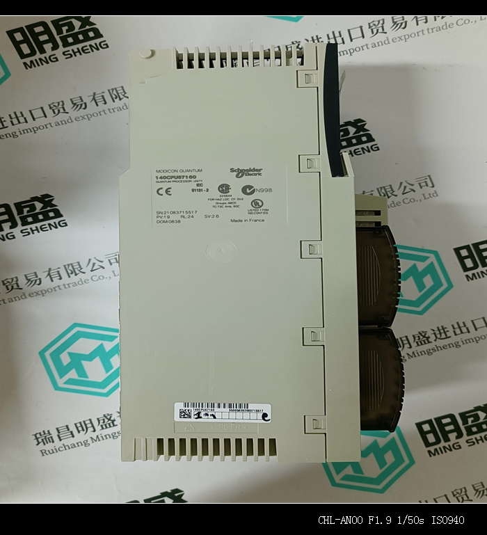


140CPU31202C工控备件PLC模块卡件
类目:140系列PLC
型号:140CPU31202C
全国服务热线:+86 15270269218
手机:+86 15270269218
微信:+86 15270269218
QQ:3136378118
Email:stodcdcs@gmail.com