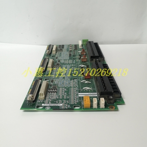
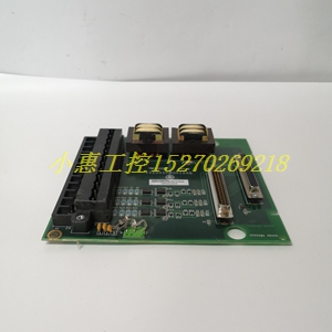
欢迎您访问:瑞昌明盛自动化设备有限公司,我司将竭诚为您服务!
IC641VPS310通用电气卡件现货

主页 > 产品中心 > GE

IC641VPS310通用电气卡件现货

类目:GE
型号:IC641VPS310
全国服务热线:+86 15270269218
手机:+86 15270269218
微信:+86 15270269218
QQ:3136378118
Email:stodcdcs@gmail.com

在线咨询
产品详情
IC641VPS310通用电气卡件现货
瑞昌明盛进出口贸易有限公司
主营DCS控制系统备件,PLC系统备件及机器人系统备件,
优势品牌:Allen Bradley、BentlyNevada、ABB、Emerson Ovation、Honeywell DCS、Rockwell ICS Triplex、FOXBORO、Schneider PLC、GE Fanuc、Motorola、HIMA、TRICONEX、Prosoft等各种进口工业零部件

IC641VPS310通用电气卡件现货 IC641VPS310通用电气卡件现货 IC641VPS310通用电气卡件现货
IC641VPS310通用电气卡件现货
IC641VPS310通用电气卡件现货
IC641VPS310通用电气卡件现货
 下面只介绍区域同步方式下的速度、张力控制和开卷区跟踪。 3.1  速度控制    每当生产完一个钢卷,为了使前一卷的带尾与后一卷的带头焊接起来,开卷区活套前的全部设备(开卷机,人口S辊)先要减速至停止;待带钢焊接完成后,机组速度再迅速升至高速,以便对活套进行充套;待充套完成后,还要降速至轧机区的速度,终与轧机区同步运行。在上述加减速过程中,为了使开卷区全体设备的速度能同步变化,就必须采用主令速度控制器。特别是在生产极薄带钢时,如设备间速度出现微小不同步,则会造成带钢张力波动,从而极易引起断带事故。为此在PLC编程中编制了一个计算主令速度的模块。其程序流程如图2所示。

3.2  张力控制 3.2.1  控制原理    如何通过6RA70让电机产生所需的张力是要解决的核心问题。其控制原理框图如图3所示。    6RA70有两种控制模式:速度控制模式和张力控制模式。当6RA70工作在张力控制模式时,人为地让速度调节器处于饱和状态,同时将所需要产生的张力折算成额定转矩的百分比TR并作为6RA70转矩调节器的转矩限幅给定;当6RA70工作于速度控制模式时,将所需要的带钢线速度折算成电机额定转速的百分比nR并作为6RA70速度调节器的速度给定,同时将所需要产生的张力折算成额定转矩的百分比Te并作为6RA70转矩调节器的转矩限幅给定。6RA70工作在哪一种控制模式,由控制器中的程序自动进行切换。 3.2.2  实现过程    开卷机点动运行时,处于速度控制模式;开卷机建立张力运行时,处于张力控制模式,产生一个反向力,相当于带钢拖着开卷机向前运行。


根据实际情况,考虑了开卷机的转矩补偿:包括空载转矩和加减速时的动态力矩。    值得一提的是,由于开卷机运行时卷径是变化的,为了能计算卷径,并维持变径时的恒张力控制,直流传动电机除了用6RA70装置控制,还配有T400工艺板。PLC将带钢和卷筒的两个测速编码器反馈值送入T400,T400就可自动计算卷径。PLC只需给定线速度和张力限幅值,T400就能通过速度调节器、力矩调节器、电流调节器使得开卷机达到给定线速度、给定张力,并保持张力恒定。    S辊和活套点动或建张运行时均处于速度控制模式,其转速给定值和转矩给定值的计算同开卷机。    活套的张力控制是通过对活套车的速度控制来实现的。该系统除考虑对加减速力矩补偿外,还考虑了对摩擦力的补偿和牵引钢丝绳的振荡阻尼等因素的补偿。    活套充套时人口S辊和出口S辊的传动电机都处于发电状态,活套电机对轧机产生制动力矩的同时,对人口S辊、开卷机产生电动力矩。活套放套时,人口S辊、活套和出口S辊的传动电机均处于发电状态,对轧机产生制动力矩。 3.3开卷跟踪 3.3.1  自动降速    在开卷区跟踪系统中,卷径信号起重要作用。开卷区的自动降速和甩尾信号均与卷径有关。根据卷径可计算出当前卷筒上的带钢剩余长度Lr。

式中,D1为当前卷径;D2:为卷筒直径;G为带钢厚度。    开卷区速度从当前速度v减速到要求的减速速度vo。所走的带钢长度为Ldec。

式中,a为减速度。

3.3.3  活套套量的计算

4  结束语    系统已于2005年3月正式投入使用。开卷区各功能自投入以来,操作习惯合理,稳定可靠,开卷区速度达到6m/s,开卷机、活套的张力稳定在3‰内,达到了全连续轧制的设计要求。广州地铁三号线体育西路站位于广州市体育西路与天河南一路所在的“T”字路口,埋置于体育西路道路正下方,穿越沿天河南一路行进的地铁一号线。体育西路现路面宽26m,规划路面宽60m,车站所处的地形较平坦,地面高程为9.57~10.61m,车站两侧大部分为多层和高层建筑物。车站所在地段地下管线密集,钻孔揭露的岩层自上而下有:人工填土层(Qml4)、砂层(Qal+pl3)、冲-洪积土层(Qal+pl3)、河湖相沉积土层(Qal3)、残积土层(Qel)、岩石全风化带、岩石强风化带、岩石中等风化带、岩石微风化带。车站总平面图如图1。 1.2 一号线体育西路站结构现状 一号线体育西路站主体结构于1997年9月竣工,车站设计为13m岛式站台、双层三跨结构。车站顶覆土约1.8m,底板埋深约14m。press, its main difference lies in the central mechanism and ejector. The central mechanism is composed of lifting cylinder, bag changing cylinder, bag cylinder and lower ring. The upper and lower ends of the capsule are fixed and can stretch up and down, so the capsule can retract the capsule barrel after the capsule enters the fetus and completes the setting and vulcanization and the tire vulcanization. The ejector is fixed on the cross beam of the vulcanizer through the base. The upper part of the movable rod is threaded and the end is hexagonal, which can be used to adjust the stroke. The ejector is mainly used to peel the capsule into the capsule barrel and complete tire unloading. The opening and closing of the sector plate are controlled by the connecting rod mechanism. There is a roller at the inner end of the connecting rod. When the roller enters the groove of the ball nose, the sector plate closes, and when the roller leaves the groove, the sector plate opens. The tire loading mechanism adopts the manipulator structure of imitation hydraulic vulcanizer, which is a pneumatic lifting rotary arm tire loader. Its lifting, turning in and out, chuck contraction and opening are completed by the cylinder. The tire loader is installed on the left and right wall panels. The manipulator moves up and down along the guide rod driven by the air cylinder through two guide rods. The four claws of the manipulator are used to lift the raw tire from the tire holder to the lower die. After shaping, the claws of the manipulator contract, and the manipulator rises and turns out to complete the whole tire loading action. The manipulator has the advantages of light and simple structure and convenient maintenance. The function of the rear inflation device is to inflate, cool and set the tire after vulcanization to prevent thermal shrinkage deformation. The pipeline system is composed of steam pipeline, air pipeline, control pipeline and inflation pipeline of rear inflation device. It is used to transport external steam, internal pressure superheated water, setting steam, cooling water, etc. The control system adopts

PLC

Control technology, motion parameters and vulcanization steps can be completed by modifying PLC program. 2. Vulcanization process of rib tire vulcanizer the whole vulcanization process can be divided into four steps: preheating capsule, tire loading, vulcanization and mold opening.