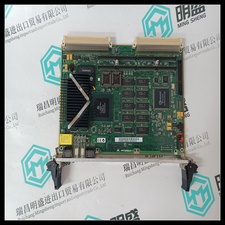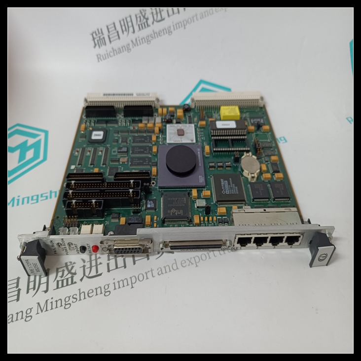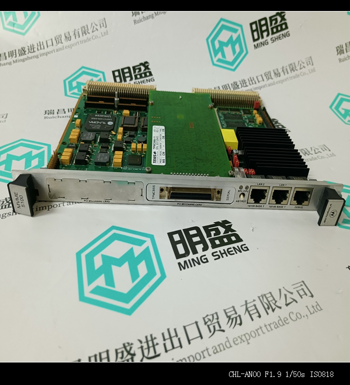

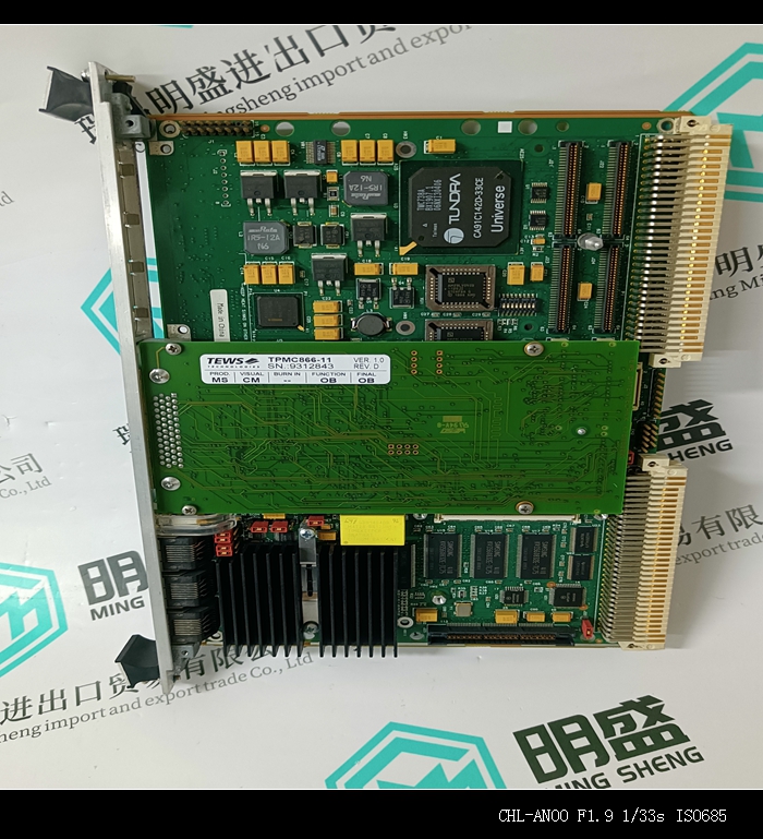


MVME172PA-642LSE自动化备件PLC系统模块现货
类目:MOTOROLA
型号:MVME172PA-642LSE
全国服务热线:+86 15270269218
手机:+86 15270269218
微信:+86 15270269218
QQ:3136378118
Email:stodcdcs@gmail.com