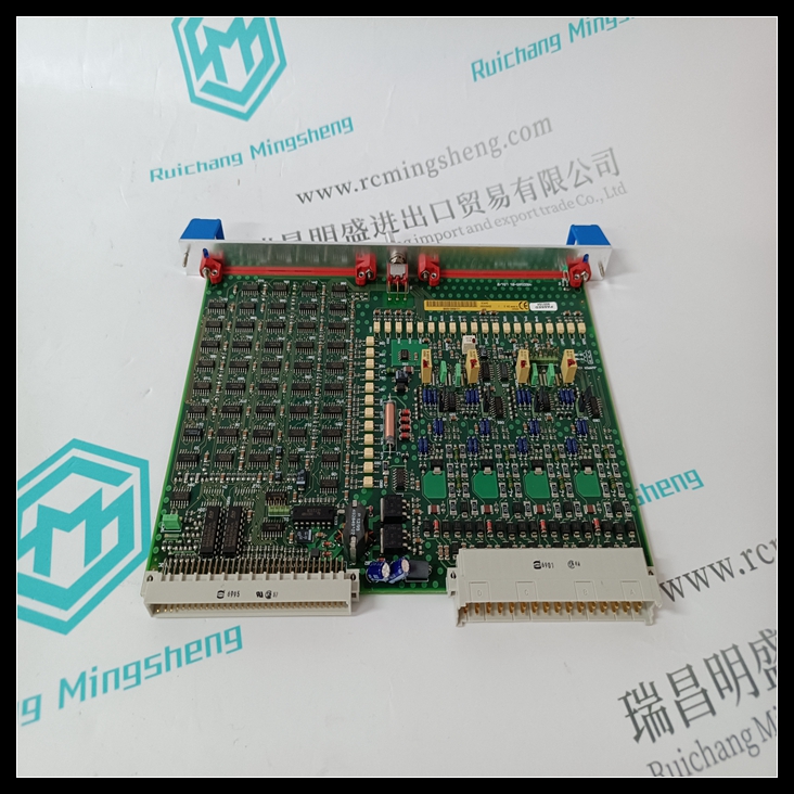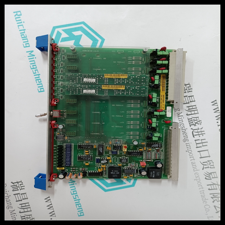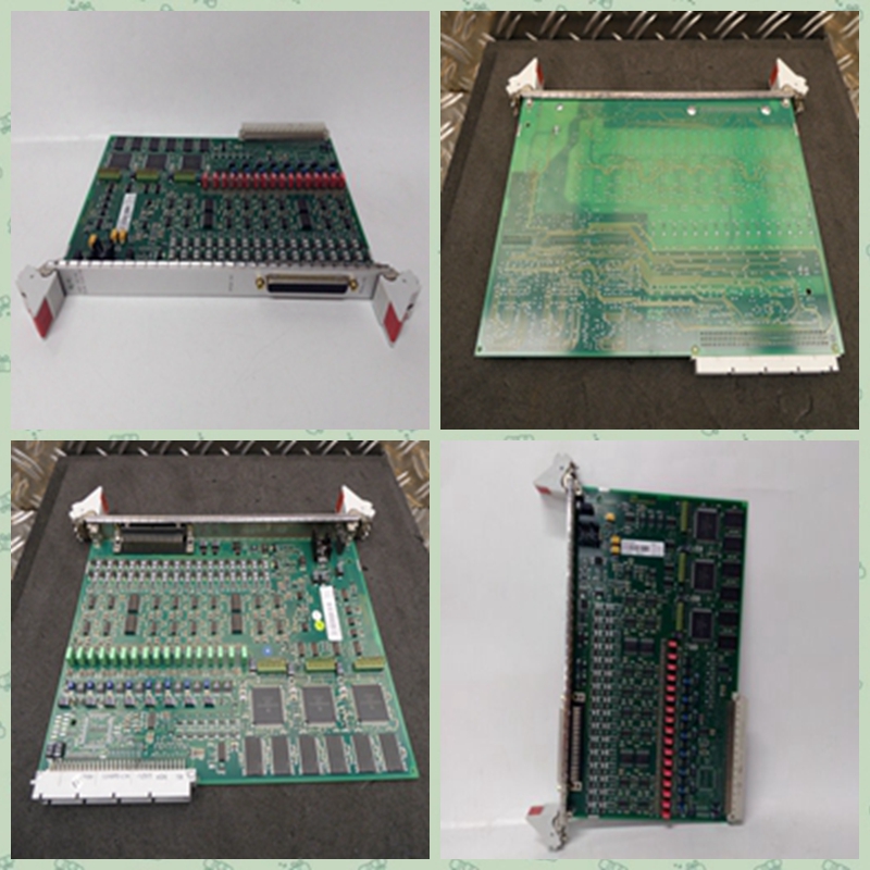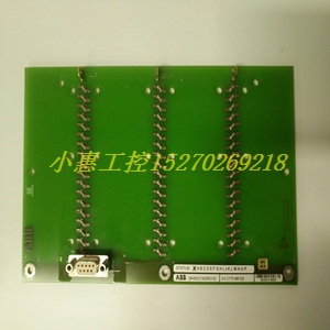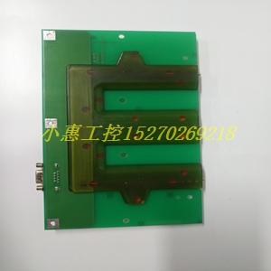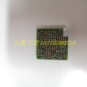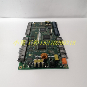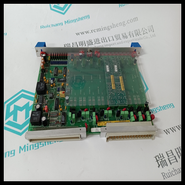

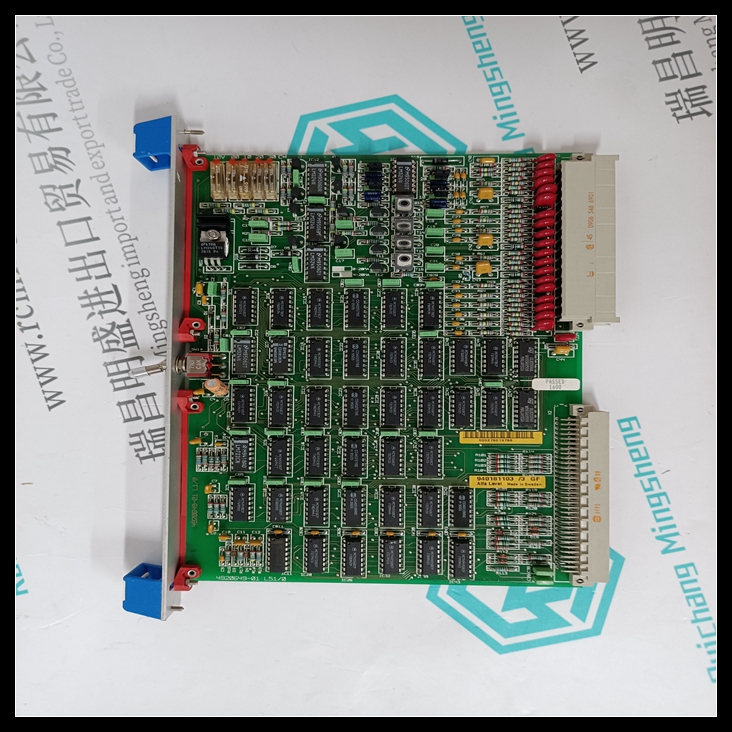

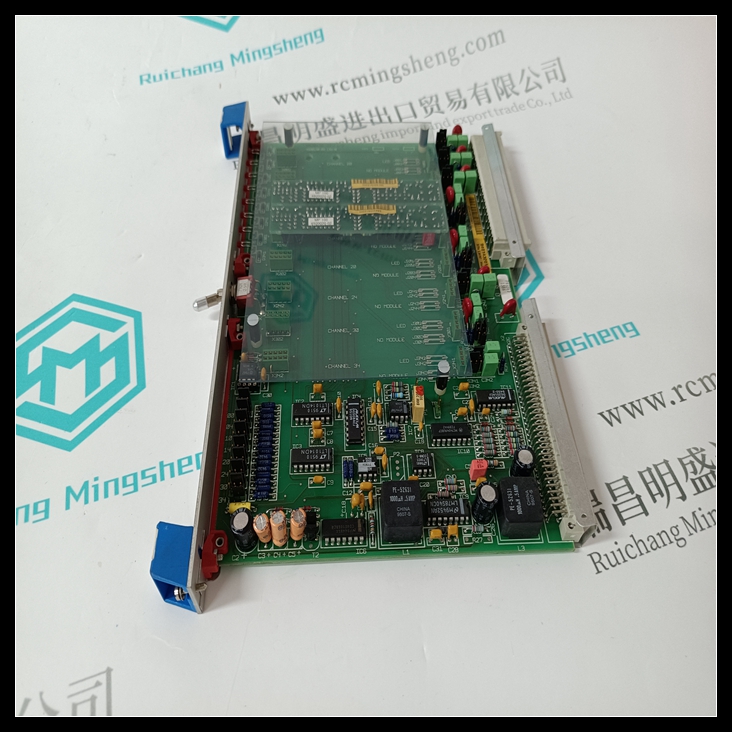
3BSE036634R1现场总线控制卡件现货
类目:ABB
型号:3BSE036634R1
全国服务热线:+86 15270269218
手机:+86 15270269218
微信:+86 15270269218
QQ:3136378118
Email:stodcdcs@gmail.com