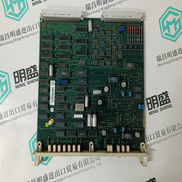

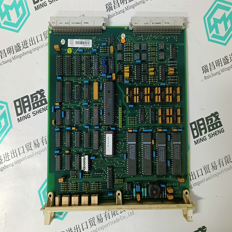
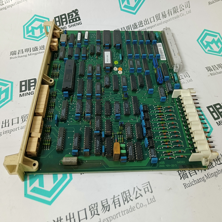
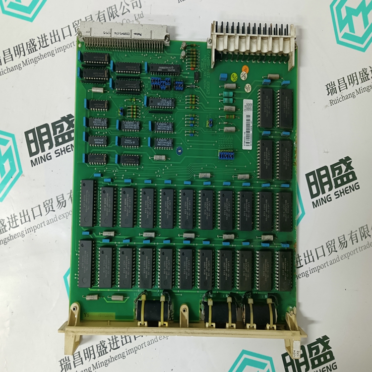
DSCA140A工业控制卡DCS模块现货
类目:ABB
型号:DSCA140A
全国服务热线:+86 15270269218
手机:+86 15270269218
微信:+86 15270269218
QQ:3136378118
Email:stodcdcs@gmail.com